Bit Bang I2C protocol
The I2C is a widely used serial bus to exchange data between two or more devices. There are many products equipped with such an interface and also several libraries to easily employ this protocol. However, the most common libraries are built to be robust and versatile. This may present limitations for some niche applications. Therefore, you may find necessary to write specific code for your project. Turns out that implementing this protocol is relatively simple and yields substantial benefits.
The problem
The I2C (or Two Wire) is a widely-used serial bus to exchange data between two or more devices (microcontrollers, sensors, displays)1. One significant advantage of this protocol is the need of just two wires that can be quite handy if your microcontroller only has 6 IO ports (an example ATtiny85). Given the popularity of this protocol, the web offers several libraries to easily implement this communication in any project but there are drawbacks: one is due to the size of these libraries, another is that the library may need the built-in peripherals present in many microcontrollers but not all of them. Despite these are not limitations for most microcontrollers we aim to write a lightweight code to implement the I2C protocol using any two digital IO ports.
How the protocol works
The I2C bus uses two wires to connect a master node with multiple slave nodes. The two wires are called Serial Data Line (SDA) and Serial Clock Line (SCL). Both lines need to be pulled up with a resistor (typically below 10k Ohms should be fine) because the master and slave will be transferring bits pulling the lines low: a logic “0” is output by pulling the line to ground, and a logic “1” is output by letting the line being pulled up by the resistors. Each slave has a 7-bit address that the master utilizes at the beginning of the communication to identify the correct device on the bus. The protocol can be split into 4 parts:
- Start Condition
- Transmission of the slave address
- Read/Write the data
- Stop condition
The start condition is defined by the SCL line being left afloat (so that it’s pulled-high by the resistors) and the SDA line pulled low by the master that wants to start the communication.
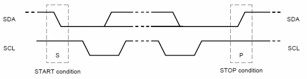 - Start and stop representation -
The stop signal is indicated by the SDA line transitioning from low to high, while the SCL line is high.
One key aspect of the protocol is that apart from the START and STOP conditions the SDA line only changes state while the clock line is low. After the START condition, the clock line will be set low by the master that changes it just to read one bit after another.
After each byte of data is transferred the receiving party will send an “acknowledge” bit stating if more data can be received or the transmission has to stop.
Required parts
The code below uses some utilities to set the SDA and SCL pins HIGH or LOW. This will depend on the used platform. The following instructions are to set the output registers for SDA and SCL HIGH or LOW:
#define SDA_ON (OUT_REG |= (1<< PI2C_SDA))
#define SDA_OFF (OUT_REG &= ~(1<< PI2C_SDA))
#define SCL_ON (OUT_REG |= (1<< PI2C_SCL))
#define SCL_OFF (OUT_REG &= ~(1<< PI2C_SCL))
Here PI2C_SDA is the pin for the SDA line and PI2C_SCL is the pin for the clock line. OUT_REG is the output register of the microcontroller (PORTA or PORTB in case of an ATMega328).
Another useful tool to define is a delay routine that controls the clock and the interval between the data bit being set. So we define the function dly() a simple “do nothing”:
inline void dly(){_NOP();};
This can instead be set to a number of microprocessor clocks or a precise timeframe but we are keeping it as simple as possible.
Start Condition
As mentioned earlier the slaves know that the communication is being initiated when the SDA line changes from HIGH to LOW while the clock is HIGH. So as a first thing we leave both lines pulled-up by the resistors, then we bring the SDA LOW and we also set the clock LOW for the next phase.
/*  i2c start sequence */
void start(){
    SDA_ON;
    dly();
    SCL_ON;
    dly();
    SDA_OFF;
    dly();
    SCL_OFF;
    dly();
}
Stop Condition
Similar as before the stop condition is as follows: set SDA low, let SCL go high, then let SDA go high as well.
/*  i2c stop sequence */
void stop(){
    SDA_OFF;
    dly();
    SCL_ON;
    dly();
    SDA_ON;
    dly();
}
Send data
Now let’s see how to send 8 bits of data. For each one of the 8 bits of data to be transferred, we need to set the SDA line to LOW if the bit is 0 or HIGH if the bit is 1. Then we change the clock to high and low again. At this point, the slaves read the SDA line and knows if the bit is 1 or 0. Then we read the ACK bit and return it. Easy.
/* Transmit 8 bit data to slave */
bool Tx(uint8_t dat){

    for(uint8_t i = 8; i; i--){
        (dat & 0x80) ? SDA_ON : SDA_OFF; //Mask for the eigth bit
        dat<<=1;  //Move
        dly();
        SCL_ON;
        dly();
        SCL_OFF;
        dly();
    }
    SDA_ON;
    SCL_ON;
    dly();
    bool ack = !SDA_READ;    // Acknowledge bit
    SCL_OFF;
    return ack;
}
Receive data
The data is transferred one byte at a time that we store in an unsigned integer of size 8 bits. We can use a for loop to read the SDA line at every clock cycle. The master sets the SCL line high and then read the SDA line. If the SDA is 1 write it into the first bit of a variable (dat in this case): if(SDA_READ) dat |=1. At every clock cycle shift the data holder one bit to the left with dat <<= 1.
Within the for loop, there is a new concept: the clock stretching. The master is in charge of driving the clock. When this requests the data the slave needs to set the SDA line high or low while the clock is low and ready for the next clock cycle. However what happens if the slave is busy and can’t take care of the I2C communication? Then he can pull the clock low until is able to resume the communication; if the master tries to release the clock and this is not pulled up by the resistors then it knows that the slave is not ready and will wait until the clock line is released.
uint8_t Rx(bool ack){
    uint8_t dat = 0;
    SDA_ON;
    for( uint8_t i =0; i<8; i++){
        dat <<= 1;
        do{
            SCL_ON;
        }while(SCL_READ == 0);  //clock stretching
        dly();
        if(SDA_READ) dat |=1;
        dly();
        SCL_OFF;
    }
    ack ? SDA_OFF : SDA_ON;
    SCL_ON;
    dly();
    SCL_OFF;
    SDA_ON;
    return(dat);
}
Putting everything together
Now we have all the ingredients to complete a conversation. Let’s say we want to send one byte of data and write it into a certain register. Then these are the steps:
- Start the comunication;
- Write to the bus the slave address;
- Tell the slave what register you want to write into;
- Send the data;
- Close the comunication.
Here it is the code:
int main(void){

    DDRB = (1<<DDB1)|(1<<DDB0); // Set the PB0 and PB1 as output

    start();
    Tx((ADDR<<1)|0x00); // Transfer the slave address plus
                        // the read write bit (write in this case)
    Tx(0x00); // Register address where we want to write
    Tx(0x01); // Data to be written
    stop();

    while(1){} // do nothing

}
Uploading this code into an ATtiny85 takes just 154 bytes of flash memory.
Now let’s go back to our original aim of reducing the program size to the bare minimum. We can compare this bit-banged I2C talking with a library commonly used within the Arduino framework. The Wiring library is one of the most common among Arduino users for SPI or I2C communication. This is not only included in the framework but also used by several sensors libraries (for example LCD screen, pressure sensors, accelerometers, etc…)
| Library | RAM Used | FLASH Used |
|---|---|---|
| Bit-bang | 0 | 154 |
| Wire.h | 41 | 724 |
| TinyWireM.h | 20 | 400 |
Conclusions
Sending 8 bits with the Wiring library needs almost 5 times more than the code we wrote! Consider that sending one byte of data using the Wiring library will occupy 10% of your ATtiny85 available program space (8KB of Flash memory); if you are also using the Arduino framework and a bootloader you are in trouble… Needless to say that the wiring library is (or at least I expect it to be) more robust and with more features. However, if you are tight with the space and an error-free communication is non-critical, you can think of implementing this simple protocol yourself. This also allows to fit the I2C protocol on the ATtiny10 that comes with just 1KB of Flash and no I2C dedicated hardware peripheral.