OLED Display driven by ATtiny10
I tried to fit the code to drive an OLED display into an ATtiny10. Is it possible? Yes! But how much space is left to actually make something useful?
The problem
Playing around with the mighty ATtiny10 I asked myself if it was capable to drive an OLED display. Why? Curiosity mainly; and also seems quite a challenge to squeeze all the code in less than 1Kb. So I gave it a go.
I used a 128x32 monochrome OLED display driven by the SSD1306 controller. This can be easily bought for few bucks assembled in handy breakout boards offering a Two-Wire Interface (I2C).
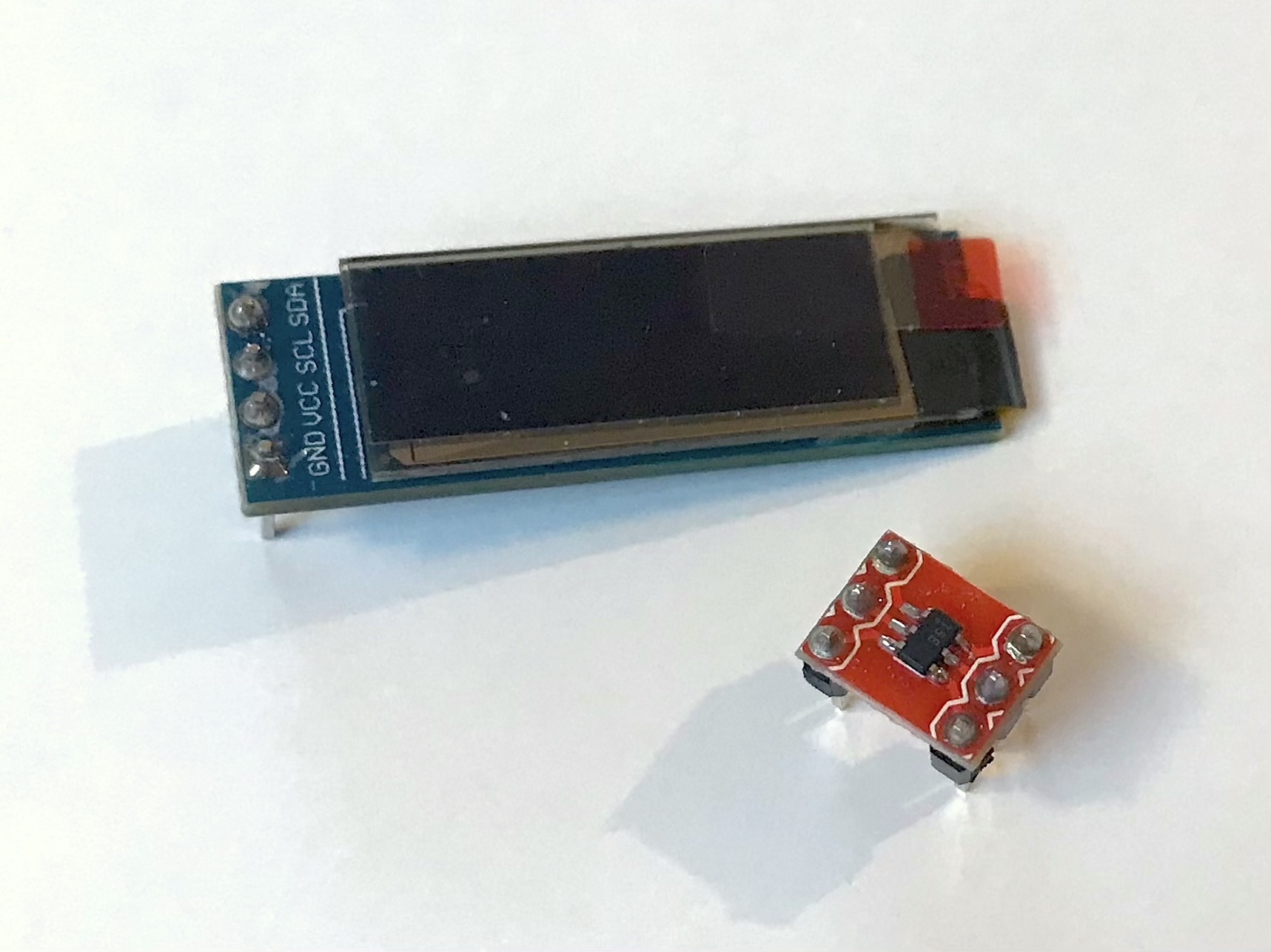 -The OLED Display used-
Needless to say that I needed to write all the code from scratch to fit it in a few kilobytes. I certainly can’t use off-the-shelf libraries: just the Wire library for the I2C protocol occupies almost all the ATtiny10 total flash memory.
So this exercise can be split into two problems:
- Implementing the I2C protocol
- Initialize the display with the right commands and data
The I2C protocol
So first thing to figure out is how to talk to the OLED SSD1306 chip. Since the ATtiny10 has no I2C dedicated peripherals I wrote some simple code to bit-bang the communication protocol. This simply consists of four functions managing the start/stop conditions and the transmission and receipt of one byte.
The I2C code I used is made of some macros and four functions. I already tried to explain all details of the code here. You can read that post if you want to understand all the bits and pieces of the code.
*  i2c start sequence */
void start(){
    SDA_ON;
    dly();
    SCL_ON;
    dly();
    SDA_OFF;
    dly();
    SCL_OFF;
    dly();
}

/*  i2c stop sequence */
void stop(){
    SDA_OFF;
    dly();
    SCL_ON;
    dly();
    SDA_ON;
    dly();
}

/* Transmit 8 bit data to slave */
bool Tx(uint8_t dat){
    for(uint8_t i = 0; i<8; i++){
        (dat & 0x80) ? SDA_ON : SDA_OFF;
        dat<<=1;
        dly();
        SCL_ON;
        dly();
        SCL_OFF;
        dly();
    }
    SDA_ON;
    SCL_ON;
    dly();
    bool ack = !SDA_READ;    // Acknowledge bit
    SCL_OFF;
    return ack;
}

/* Receive 8 bit of data from the slave */
uint8_t Rx(bool ack){
    /* implemented but not used for the OLED display */
}
The I2C follows this protocol:
- start the communication
- send the address of the device plus read/write bit
- send/receive the data
- stop the communication
Sending one byte of data using the code above takes approximately 130 bytes. Now I can talk with the display. What do I tell?
OLED configuration
To initiate the communication, the ATtiny will fire the start condition and send the SSD1306 7bit address followed by a read/write bit (0 to write and 1 to read).
The SSD1306 address is either 0b0111100 or 0b0111101. Since I mostly want to send data, this will be followed by a zero.
According to the SSD1306 datasheet 1, the second byte to be transferred is a control byte: this defines if the following data will be configuration commands or data to be displayed.
- Commands:
0x00 - Data:
0x40
Every comunication with the OLED will be similar to this:
start();         //Start Condition
Tx(0b01111000);  //Address plus write bit
Tx(0x00);        //Send 0x00 for commands or 0x40 for data
Tx(command_1);
/* all other data bytes */
Tx(command_N);
stop();
The OLED initialization requires a bunch of commands. I commented the ones I used in the code below. However these are better explained in the datasheet 1.
/* OLED initialization commands */
0xAE,         // Display OFF
0xA8, 0x1F,   // set multiplex (HEIGHT-1): 0x1F for 128x32, 0x3F for 128x64
0xD3, 0x00,   // Display offset to 0
0x40,         // Set display start line to 0
0x8D, 0x14,   // Charge pump enabled
0x20, 0x00,   // Memory addressing mode 0x00 Horizontal 0x01 Vertical
0xDA, 0x02,   // Set COM Pins hardware configuration to sequential
0x81, 0x80,   // Set contrast
0xD9, 0xF1,   // Set pre-charge period
0xDB, 0x40,   // Set vcom detect

0x22, 0x00, 0x03, // Page min to max
0x21, 0x00, 0x7F, // Column min to max

0xA5,   // Entire display ON  A5 Enable / A4 Disable

0xAF  // Display on
The command 0xA5 will light all the pixels of the OLED matrix irrespective of the RAM content. The image below is the result.
 -The OLED is alive-
Up to this point, 160 bytes of memory are occupied.
Clear the screen
When the display is first turned ON, the content of the RAM is completely random. So it will show pixels randomly turned on.
 -The OLED not yet cleared-
Before writing something I needed to turn OFF each pixel meaning write zeros to the controller RAM memory. The 128x32 display memory is organised in 128 columns each made by 4 pages (or rows) with a height of 8 bits. In the horizontal addressing mode (that I set in the initialization), when the RAM is written the pointer automatically is increased by 1 and when the end is reached it will start from 0 again.
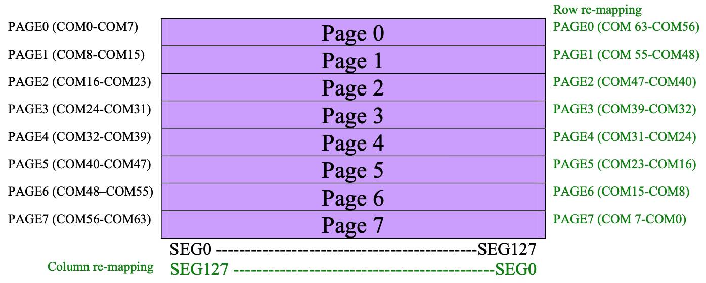 - From the datasheet. It shows the 128x64 display so there are 8 pages instead of 4-
To clear the display, I sent the command 0x00 for 128x4 times (or 256x2 will produce the same result).
start();
Tx(0b01111000);  // OLED Address
Tx(0x40);  //Send Data
for (uint8_t i = 0; i < 128; i++)
{
    Tx(0x00);
    Tx(0x00);
    Tx(0x00);
    Tx(0x00);
}
stop();
To have a display completely cleared, I occupied approximately 200 bytes.
Draw Something
Next, I tried to draw something on the screen. The logic is the same as clearing the display. Instead of sending 0s I wrote also 1s organized in bytes. Each byte represents one column in the page.
The number zero in hexadecimal bitmap is something similar to this:
 - Example of number zero bitmap -
uint8_t zero[7] = {0x3c,0x42,0x81,0x81,0x81,0x42,0x3c};
Take as an example the first column. The first two pixels (or bits) of the upper byte are ON so it’s 3 in hex. The lower byte has the last two pixels ON so in hexadecimal is C. The column is then represented in hex by 0x3C.
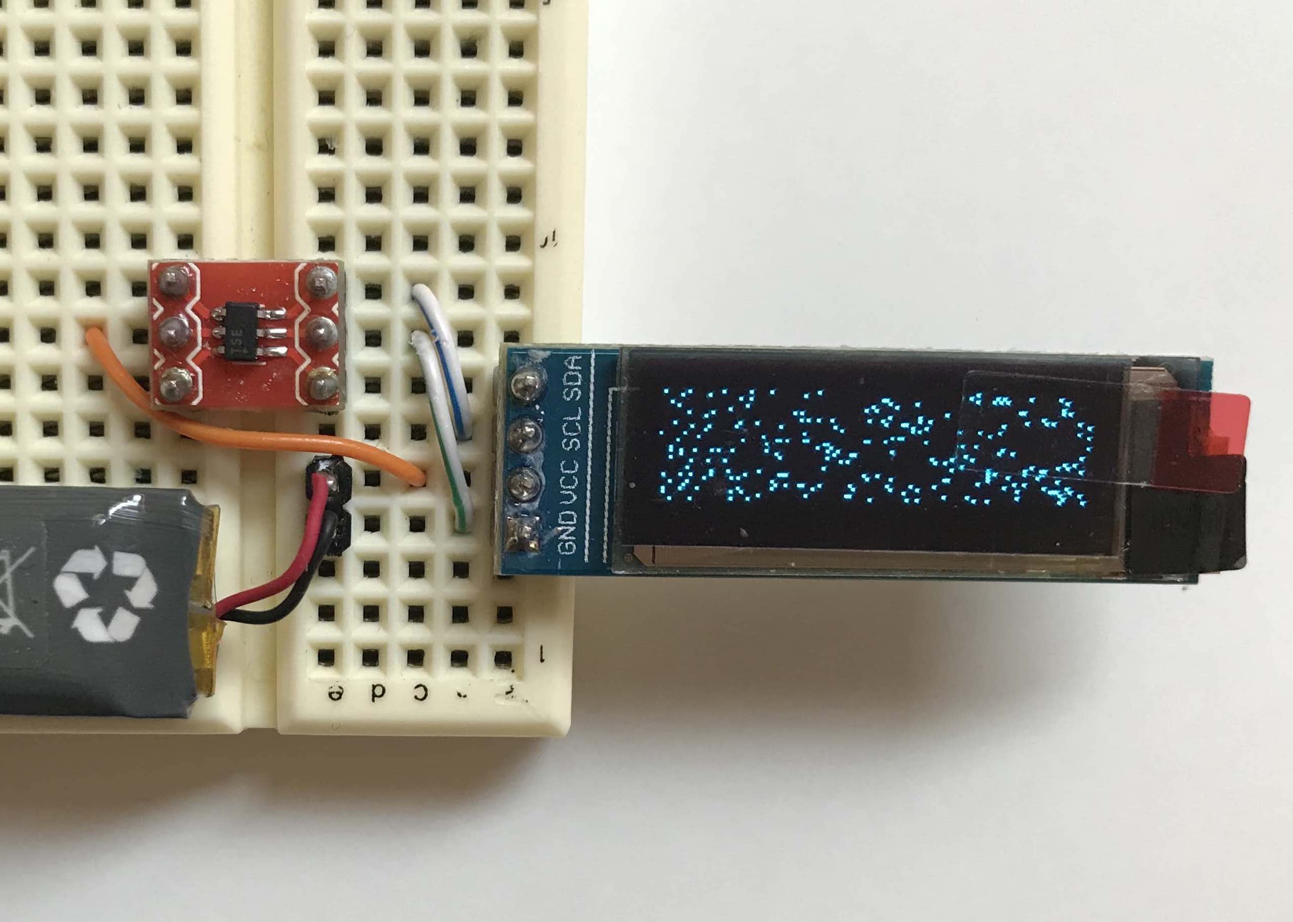
So I spent some time figuring out how to represent some letters bitmap (I actually wrote a simple visual tool in JavaScript). I placed the sequence of letters in an array.
And here is the code:
start();
Tx((ADDR<<1)); //ADDR is 0b0111100
Tx(0x40);
for (uint8_t i = 0; i < 70; i++)
{
    Tx(HELLO[i]);
}
stop();
Where the bitmap used is the following:
const uint8_t HELLO[70] ={
    0xff,0x08,0x08,0x08,0x08,0xff,0x00, //H
    0xff,0x89,0x89,0x89,0x89,0x81,0x00, //E
    0xff,0x80,0x80,0x80,0x80,0x80,0x00, //L
    0xff,0x80,0x80,0x80,0x80,0x80,0x00, //L
    0x3c,0x42,0x81,0x81,0x81,0x42,0x3c, //O
    0x00,0x00,0x00,0x00,0x00,0x00,0x00, //' '
    0x01,0x01,0x01,0xff,0x01,0x01,0x01, //T
    0x00,0x81,0x81,0xff,0x81,0x81,0x00, //I
    0xff,0x02,0x04,0x08,0x10,0xff,0x00, //N
    0x01,0x06,0x08,0xf0,0x08,0x06,0x01  //Y
};
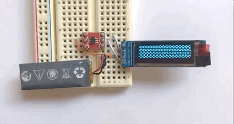
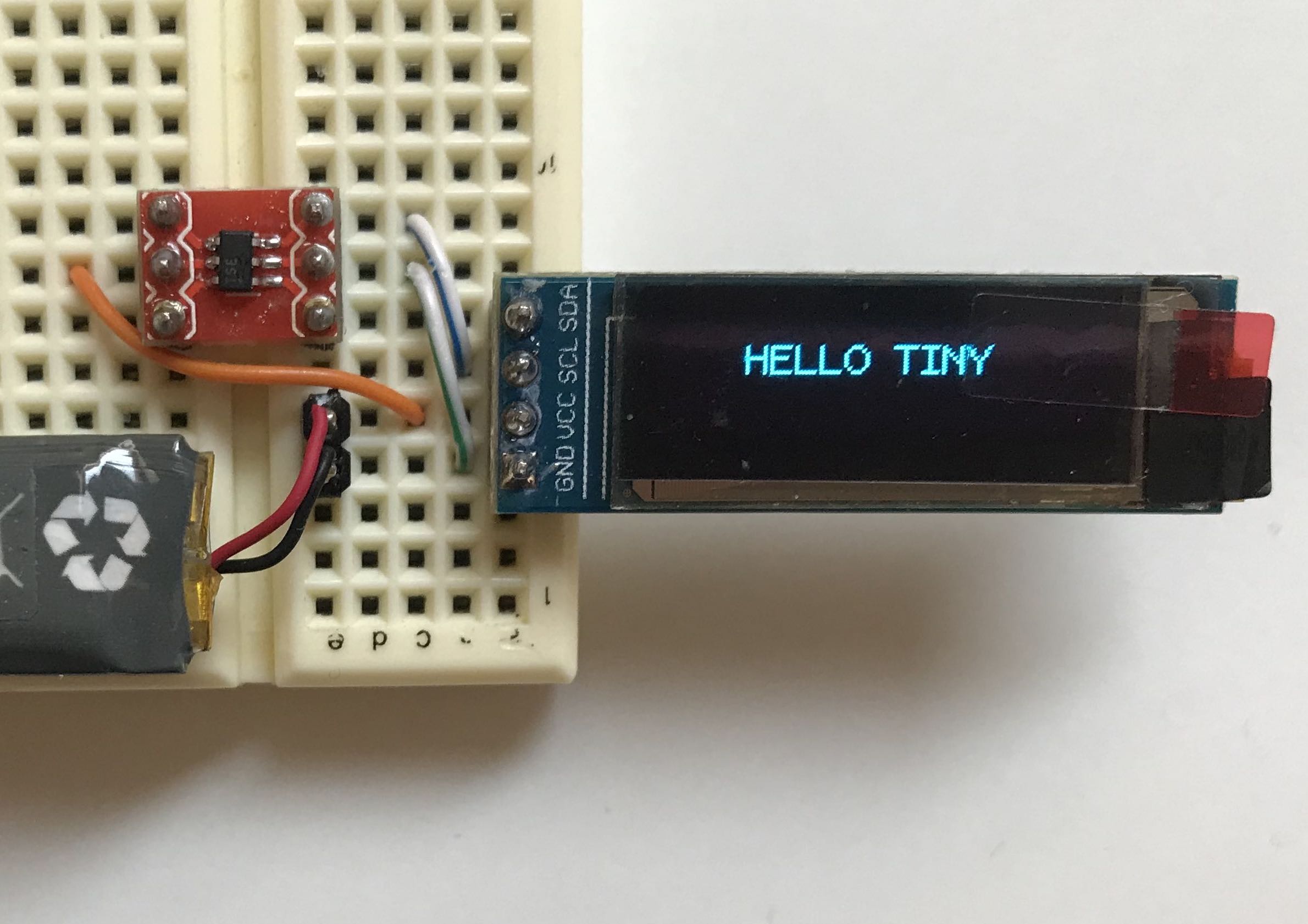 - Message written with the ATTiny10 -
I include below the full code. All this occupies 350 bytes.
#include <avr/io.h>
#include <stdint.h>
#include <util/delay.h>

#define PI2C_SDA    PB0
#define PI2C_SCL    PB1

#define OUT_REG PORTB
#define IN_REG PINB

#define SDA_ON (OUT_REG |= (1<< PI2C_SDA))
#define SDA_OFF (OUT_REG &= ~(1<< PI2C_SDA))
#define SCL_ON (OUT_REG |= (1<< PI2C_SCL))
#define SCL_OFF (OUT_REG &= ~(1<< PI2C_SCL))

#define SDA_READ (IN_REG & (1<<PI2C_SDA))
#define SCL_READ (IN_REG & (1<<PI2C_SCL))

#define I2C_READ 0x01
#define I2C_WRITE 0x00

#define ADDR 0b01111000 //OLED Address plus write bit

inline void dly(){__asm__("NOP");};

const uint8_t InitLen = 26;

const uint8_t Init[InitLen] = {
  0xAE,         // Display OFF
  0xA8, 0x1F,   // set multiplex (HEIGHT-1): 0x1F for 128x32, 0x3F for 128x64
  0xD3, 0x00,   // Display offset to 0
  0x40,         // Set display start line to 0
  0x8D, 0x14,   // Charge pump enabled
  0x20, 0x00,   // Memory addressing mode 0x00 Horizontal 0x01 Vertical
  0xDA, 0x02,   // Set COM Pins hardware configuration to sequential
  0x81, 0x80,   // Set contrast
  0xD9, 0xF1,   // Set pre-charge period
  0xDB, 0x40,   // Set vcom detect

  0x22, 0x00, 0x03, // Page min to max
  0x21, 0x00, 0x7F, // Column min to max

  0xAF  // Display on
};

const uint8_t HELLO[70] ={
    0xff,0x08,0x08,0x08,0x08,0xff,0x00, //H
    0xff,0x89,0x89,0x89,0x89,0x81,0x00, //E
    0xff,0x80,0x80,0x80,0x80,0x80,0x00, //L
    0xff,0x80,0x80,0x80,0x80,0x80,0x00, //L
    0x3c,0x42,0x81,0x81,0x81,0x42,0x3c, //O
    0x00,0x00,0x00,0x00,0x00,0x00,0x00, //' '
    0x01,0x01,0x01,0xff,0x01,0x01,0x01, //T
    0x00,0x81,0x81,0xff,0x81,0x81,0x00, //I
    0xff,0x02,0x04,0x08,0x10,0xff,0x00, //N
    0x01,0x06,0x08,0xf0,0x08,0x06,0x01  //Y
};


// I2C Functions declaration
void start();
void stop();
bool Tx(uint8_t);
uint8_t Rx(uint8_t);

int main(void){

    DDRB = 3;

    _delay_ms(100);

    /* Display Initialization */
    start();
    Tx(ADDR);
    Tx(0x00);
    for (uint8_t i = 0; i < InitLen; i++)
    {
        Tx(Init[i]);
    }

    stop();


    /* Clear the display */
    start();
    Tx(ADDR);
    Tx(0x40);
    for (uint8_t i = 0; i < 128; i++)
    {
        Tx(0x00);
        Tx(0x00);
        Tx(0x00);
        Tx(0x00);
    }
    stop();

    /* Set position for the text */
    start();
    Tx(ADDR);
    Tx(0x00);
    Tx(0x21);   // Set Column
    Tx(0x19);   // Start at column 25
    Tx(0x7F);   // End at 128
    Tx(0x22);   // Set Page
    Tx(0x01);   // Start at page 1
    Tx(0x01);   // End at page 1
    stop();

    /* Write the message*/
    start();
    Tx(ADDR);
    Tx(0x40);
    for (uint8_t i = 0; i < 70; i++)
    {
        Tx(HELLO[i]);
    }
    stop();

    for(;;){ }

}


/*  i2c start sequence */
void start(){
    SDA_ON;
    dly();
    SCL_ON;
    dly();
    SDA_OFF;
    dly();
    SCL_OFF;
    dly();
}


/*  i2c stop sequence */
void stop(){
    SDA_OFF;
    dly();
    SCL_ON;
    dly();
    SDA_ON;
    dly();
}

/* Transmit 8 bit data to slave */
bool Tx(uint8_t dat){
    for(uint8_t i = 0; i<8; i++){
        (dat & 0x80) ? SDA_ON : SDA_OFF;
        dat<<=1;
        dly();
        SCL_ON;
        dly();
        SCL_OFF;
        dly();
    }

    SDA_ON;
    SCL_ON;
    dly();
    bool ack = !SDA_READ;    // Acknowledge bit
    SCL_OFF;
    return ack;
}

/* Receive 8 bit packet data from the slave. Check for clock stretching*/
uint8_t Rx(bool ack){
    uint8_t dat = 0;
    SDA_ON;
    for( uint8_t i =0; i<8; i++){
        dat <<= 1;
        do{
            SCL_ON;
        }while(SCL_READ == 0);  //SCL stretching
        dly();
        if(SDA_READ) dat |=1;
        dly();
        SCL_OFF;
    }
    ack ? SDA_OFF : SDA_ON;
    SCL_ON;
    dly();
    SCL_OFF;
    SDA_ON;
    return(dat);
}
Some animations
Then I tried the scrolling feature of the OLED controller. It needs no further computation from the Attiny10 apart from sending a few commands.
With the following commands I set the scolling from left to right for all the four pages.
// start();
// Tx((ADDR<<1));
// Tx(0x00);
// Tx(0x26);   // Scroll horizontally
// Tx(0x00);   // Dummy byte
// Tx(0x00);   // Start Page 0
// Tx(0x00);   // Frames
// Tx(0x04);   // End Page 3
// Tx(0x00);   // Dummy byte
// Tx(0xFF);   // Dummy byte
// Tx(0x2F);   // Activate Scrolling
// stop();
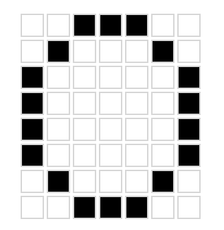
Then I filled the RAM with a repeated pattern and here it is the result:
 - Pattern OLED animation -
Conclusions
Writing a few letters to an OLED display takes just above 300 bytes.
This leaves the remaining 600 bytes of space to be filled with fun and creativity.
Further work I will probably do on this is to optimize and reduce the space used by the I2C functions. Probably writing it in assembly.
Next is to think of some nice ways to use it and maybe put everything on a custom PCB.
In case you have ideas on what to do with an OLED and an ATtiny10 let me know. I hope I suggested some ideas to people more creative than I am.
Other posts you may be interested in
- Tiny videogame for the ATtiny10
- Bit Bang I2C protocol
- ATtiny10 Programming with Platformio and Terminal