Programming the ATtiny 1-series
Getting started with the AVR ATtiny 1-series microcontrollers in an easy and inexpensive way. Compilation and firmware upload with PlatformIO and a USB to serial adapter.
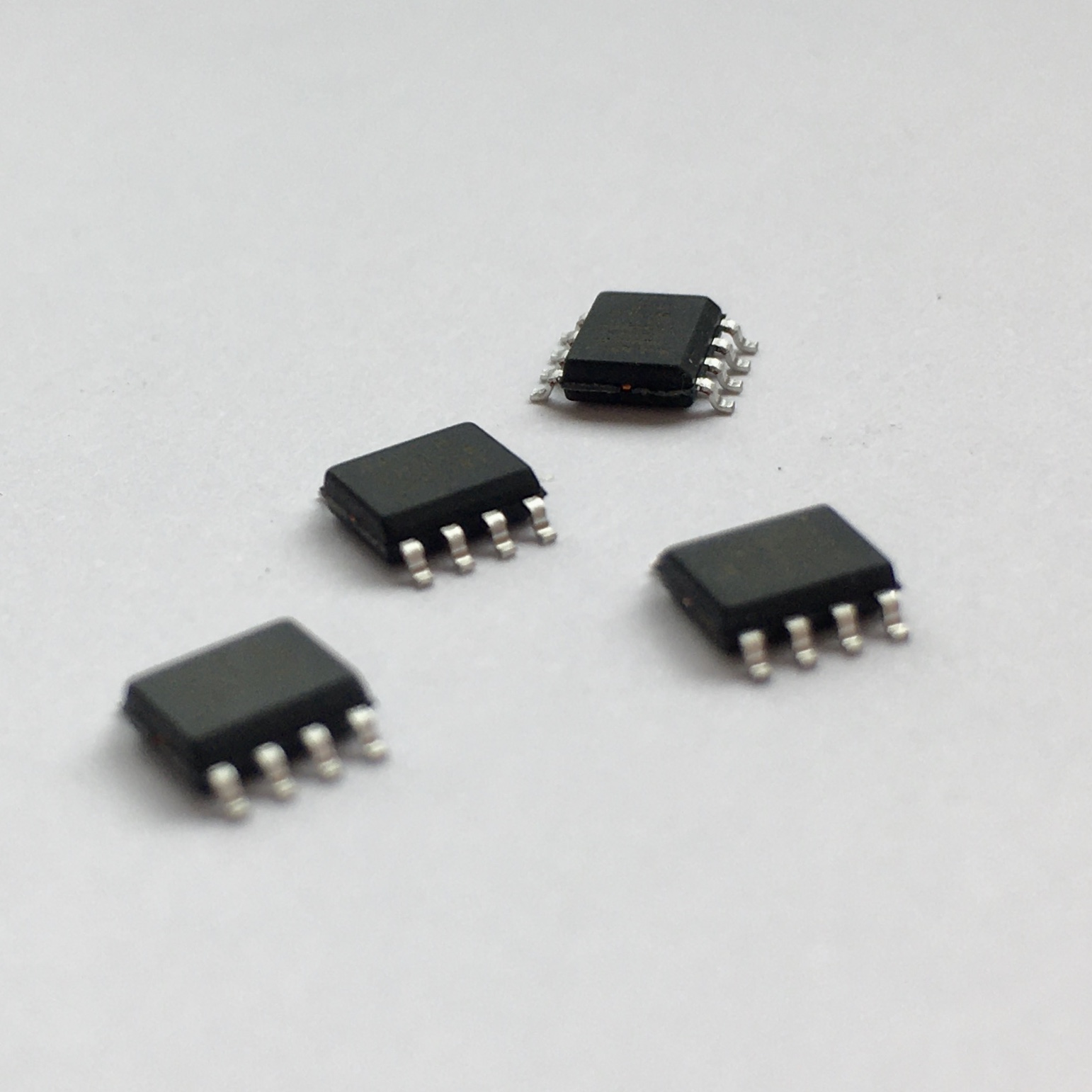
I’m a great fan of the ATtiny85 and used it in several simple small projects. However, I recently started playing with some of the ATtiny 1-series and shortly after, happily replaced the old ATtiny85. I started with the small ATtiny412 1 but the whole device family offers a large number of features that vastly simplify the design process compared to the older devices. To name a few: one-wire UPDI flashing/debugging interface, port multiplexing, RTC, configurable custom logic, capacitive-touch sensing, various voltage references and more.
Most importantly, though, they are a lot cheaper! Roughly speaking they cost half of the comparable older device 2.
These chips use a programming and debugging interface called UPDI - Unified Program and Debug Interface - that needs just three wires: GND, VCC and data (instead of 6 as the ISP). Being a relatively new interface the available documentation is limited in comparison to other devices and getting started may not be straightforward. Therefore I collected some information and I will show the setup I use to program these chips from the code compilation to the firmware uploading. There are other approaches illustrated on the web 3 but I find this setup the most convenient.
Overview of the process and material needed
I will show the workflow for the ATtiny412 but it can be adapted for any device of the series.
First thing to sort out is building the firmware. Most of the AVR toolchain around (i.e. the ones available with Arduino or PlatformIO IDE) don’t have the required libraries to compile the code for these new chips. So, unless you are using Atmel Studio 7, you need to manually install them.
Then, I will show how to set up a new board on PlatformIO IDE. This is just a matter of preference: the code can also be compiled with avr-gcc from terminal.
To upload the firmware into the ATtiny412, I’m using a UPDI programmer based on a Python script - pyupdi - that communicates to the AVR chip through a USB to TTL serial adapter.
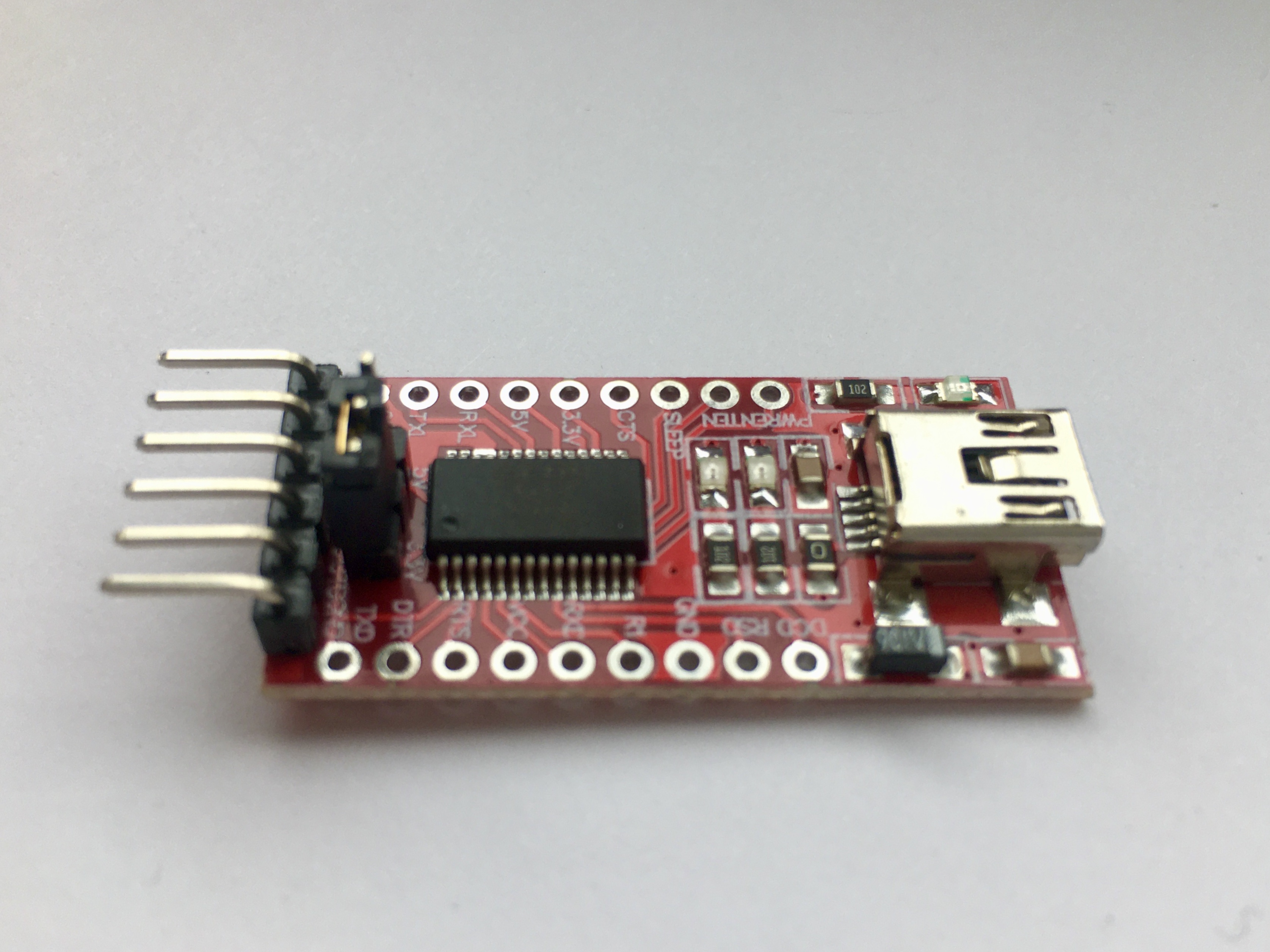 - A common and cheap USB to serial adapter can be used to program the chips -
Any maker likely has one or more serial adapters lying around and, if not, can be purchased on eBay for few cents. Other solutions involve buying expensive programmers, building one or converting an Arduino into a programmer. I find using pyupdi simpler and way cheaper.
Adding the new AVR libraries
When I started using the ATtiny412, my AVR toolchain didn’t have the libraries needed. The compiler, avr-gcc, is on the other hand up-to-date. So he knows about the devices but couldn’t find the libraries giving this warning alongside not recognising the device-specific instructions:
warning: #warning "device type not defined"
To solve it you need to download the libraries and place them in the right folders.
Download the libraries
Finding the required files on the web has been not an easy task. Thankfully the Atmel application note AN2503 has been a good starting point 4.
The files can be downloaded from this [link](https://packs.download.microchip.com/.
The pack of our interest is the latest Atmel ATtiny Series Device Support.
It’s a .atpack, but it’s actually a zipped folder. So you can open it changing it’s extension into .zip.
Copy files in the right directories
From the unzipped folder copy all the files from include/avr to
[PlatformIO folder]/packages/toolchain-atmelavr/avr/include/avr/
Then copy all the files *.o and *.a from each folder named gcc/dev/attiny* (or just the ones you need) to the folders in
[PlatformIO folder]/packages/toolchain-atmelavr/avr/lib/
following the same folder structure.
So for example, for the ATtiny412 there are two files inside /gcc/dev/attiny412/avrxmega3/short-calls/. These will be placed inside
[PlatformIO folder]/packages/toolchain-atmelavr/avr/lib/avrxmega3/short-calls/
As an alternative in Unix you can use the following commands 5:
$ sudo cp include/avr/iotn?*1[2467].h [PlatformIO folder]/packages/toolchain-atmelavr/avr/include/avr/
$ sudo cp gcc/dev/attiny?*1[2467]/avrxmega3/*.{o,a} [PlatformIO folder]/packages/toolchain-atmelavr/avr/lib/avrxmega3/
$ sudo cp gcc/dev/attiny?*1[2467]/avrxmega3/short-calls/*.{o,a} [PlatformIO folder]/packages/toolchain-atmelavr/avr/lib/avrxmega3/short-calls/
Add headers into io.h
Locate the io.h file inside you avr toolchain folder. For PlatformIO this is
[PlatformIO folder]/packages/toolchain-atmelavr/avr/include/avr/io.h
Copy the code below in the similar section where all the headers are defined.
#elif defined (__AVR_ATtiny212__)
#  include <avr/iotn212.h>
#elif defined (__AVR_ATtiny412__)
#  include <avr/iotn412.h>
#elif defined (__AVR_ATtiny214__)
#  include <avr/iotn214.h>
#elif defined (__AVR_ATtiny414__)
#  include <avr/iotn414.h>
#elif defined (__AVR_ATtiny814__)
#  include <avr/iotn814.h>
#elif defined (__AVR_ATtiny1614__)
#  include <avr/iotn1614.h>
#elif defined (__AVR_ATtiny3214__)
#  include <avr/iotn3214.h>
#elif defined (__AVR_ATtiny416__)
#  include <avr/iotn416.h>
#elif defined (__AVR_ATtiny816__)
#  include <avr/iotn816.h>
#elif defined (__AVR_ATtiny1616__)
#  include <avr/iotn1616.h>
#elif defined (__AVR_ATtiny3216__)
#  include <avr/iotn3216.h>
#elif defined (__AVR_ATtiny417__)
#  include <avr/iotn417.h>
#elif defined (__AVR_ATtiny817__)
#  include <avr/iotn817.h>
#elif defined (__AVR_ATtiny1617__)
#  include <avr/iotn1617.h>
#elif defined (__AVR_ATtiny3217__)
#  include <avr/iotn3217.h>
Modify file avrxmega3.xn
Open the file
[PlatformIO folder]/packages/toolchain-atmelavr/avr/lib/ldscripts/avrxmega3.xn
Replace the line 19 from:
data (rw!x) : ORIGIN = 0x802000, LENGTH = __DATA_REGION_LENGTH__
to
data (rw!x) : ORIGIN = __DATA_REGION_ORIGIN__, LENGTH = __DATA_REGION_LENGTH__
This helps the linker correctly set the data region6.
Setting up the programming interface
Install pyupdi
As mentioned earlier, I use pyupdi, a Python script that allows to program the AVR devices using a standard TTL serial port. You can get it from GitHub at this page or install with pip:
pip install https://github.com/mraardvark/pyupdi/archive/master.zip
The usage is simple. The following command will show you the information of the connected ATtiny412:
pyupdi -d tiny412 -c /dev/cu.usbserial-**** -i
The option -d specifies the device while-c defines the com port where the serial adapter is connected. You can find it with the command ls /dev/cu* or from Device manager in Wondows.
Connect the ATtiny
This is the list of hardware needed to connect the ATtiny to a computer:
- FTDI adapter
- Jumper cables
- 4.7k resistor
The connections are the following:
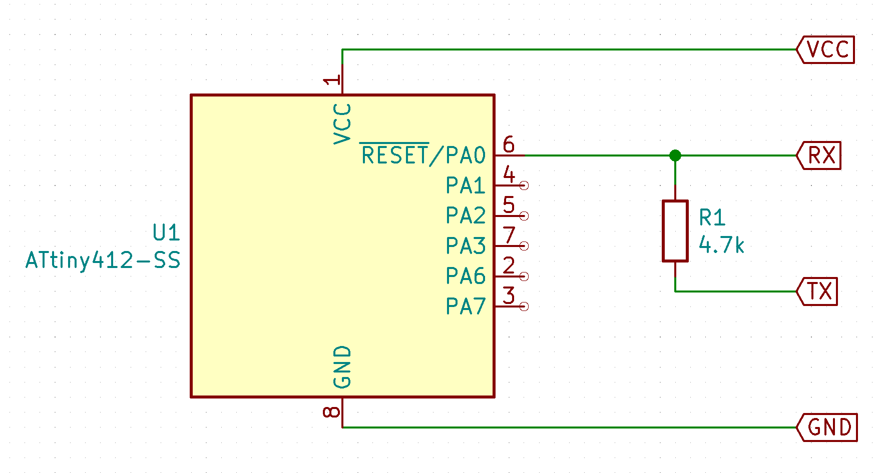
Select 3.3v output with the jumper on the FTDI chip.
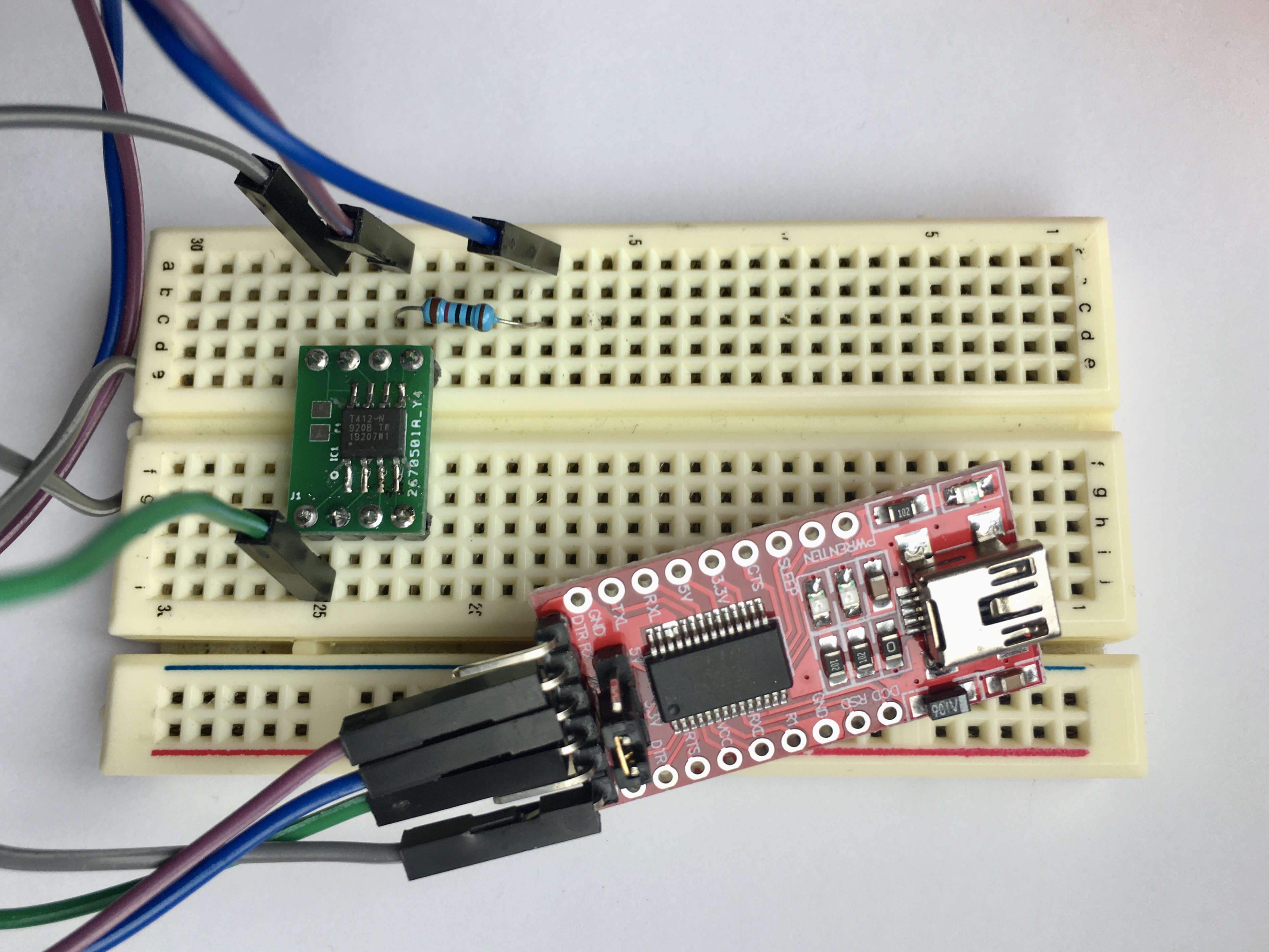 - Complete setup needed to program the ATtiny412 -
Setting up the PlatformIO environment
Create a new board
PlatformIO unfortunately still doesn’t support for the AVR 1-series, so you need to create a new board. Luckily, it’s easy.
Create a new file attiny412.json with the code below and place it into the folder [PlatformIO folder]/boards.
{
  "build": {
    "f_cpu": "3300000UL",
    "mcu": "attiny412"
  },
  "name": "ATtiny412",
  "upload": {
    "maximum_ram_size": 256,
    "maximum_size": 4096,
  },
  "url": "https://www.microchip.com/wwwproducts/en/ATtiny412",
  "vendor": "Atmel"
}
For a different device, just use the appropriate parameters.
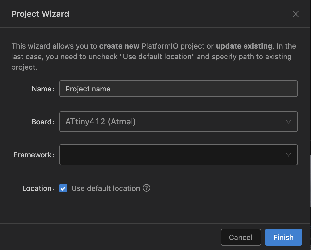
Now you can select the ATtiny412 when you create a new project from PlatformIO home page.
Modify the platformio.ini file
Last thing left to do is to tell PlatformIO to use pyupdi changing the platformio.ini configuration file in the project folder:
[env:attiny412]
platform = atmelavr
board = attiny412
upload_flags =
    -dtiny412
upload_port = [your serial port]
upload_command = pyupdi $UPLOAD_FLAGS -c $UPLOAD_PORT -e -f $SOURCE
The upload_port variable has to be replaced with the port the serial adapter is connected to. This can be found using the command /dev/cu* for Linux and macOS.
Upload a test program
Inside PlatformIO project src folder, create a main.c file to test the ATtiny:
#include <avr/io.h>
#include <util/delay.h>

int main()
{
    PORTA.DIR = PIN1_bm;    // Set pin 4 as output
    while(1){
        PORTA.OUTTGL = PIN1_bm; // Toggle state of pin 4
        _delay_ms(200);
    }
}
This will blink a led connected on pin 4.
Hit Upload and, if everything goes well, you should have a led blinking on pin 4.
Other posts you may be interested in
- Smallest game console fits into an ATtiny10
- ATtiny10 Programming with Platformio and Terminal
- OLED Display driven by ATtiny10
Notes
-
Link to the datasheet ↩
-
At the time of writing an ATtiny85 (8 I/O) from Digikey in one unit is about £0.92. An ATtiny814 (12 I/O) is £0.48. An ATtiny817 (22 I/O) is £0.67. ↩
-
Examples on Technoblogy and JayCarlson. GitHub page of Jtag2UPDI. ↩
-
Page 14 of the Application Note shows the link to the libraries download page. ↩