ATtiny85 push-button power switching: software-only solution
How do you power ON and OFF a microcontroller without a switch and complex electronics? The simplest solution is to use a low power sleep mode and a few lines of code.
The problem
How do you switch ON and OFF a battery-powered circuit? I never thought this would be an issue until I wanted to power on and off an ATtiny85 based circuit to save the battery. After looking around the web for a few minutes I realized this had no obvious solution. I soon identified three main options. However, each one has it’s own pros and cons:
- Mechanical switch: very simple and effective but switches may be expensive and - let’s say - they are old fashioned;
- Latch circuit: fascinating and elegant but complex to implement and requires several passive components;
- Software on/off switching: cheap, requires no extra components, moves the complexity on the software side.
I wanted the electronics cheap and use the least components, so I went for the software switching option. In a few lines of code, I had a working code but still needed some trials before getting it right.
If you work with microcontrollers there will be a point you need this code. I hope the notes below will help.
The solution
The software switching option leverages the sleep modes offered by the AVR microcontrollers. In fact, in power-down mode, these microcontrollers consume just a few micro amps1. This current is low enough to be almost negligible2.
A momentary pushbutton can be used to interact with the microcontroller but a sensor will work as well. When the microcontroller is sleeping, a pin change interrupt is used to wake it up.
You can achieve different behaviours based on the project requirements. Examples:
- push and immediate on/off;
- push and hold to switch state;
- push on and automatic off (and vice versa);
Each project will have its own requirement. One benefit of the software solution is that you can change the behaviour of the system without intervention on the schematics.
Below I propose two codes that show the program logic3 for powering on and off an ATtiny85: the first allows for an immediate push on / push off. The second, slightly more complex, shows a push and hold pattern to switch power after a certain time.
The code is thought for an ATtiny85 but can easily be adapted to other AVR devices since most of the commands are handled through generic AVR libraries.
Setup
Microcontroller Configuration
Whatever microcontroller you use it needs to be set up to handle the external interrupts. These are commands for the ATtiny85:
PORTB |= (1 << BTN);  // Enable PULL_UP resistor
GIMSK |= (1 << PCIE); // Enable Pin Change Interrupts
PCMSK |= (1 << BTN);  // Use PCINTn as interrupt pin
sei();                // Enable interrupts
Here BTN is the I/O pin connected to the button.
And these are the commands used to set up the power-down sleep mode:
cli();                  // Disable Interrupts before next commands
wdt_disable();          // Disable watch dog timer
set_sleep_mode(SLEEP_MODE_PWR_DOWN); // Set sleep mode power down
sleep_enable();
sleep_bod_disable();    // Disable Brown out detector
sei();                  // Enable interrupts
To minimise the power consumption during the sleep mode I disabled the watchdog timer and the brown-out detector.
Hardware Setup
The circuit is very basic:
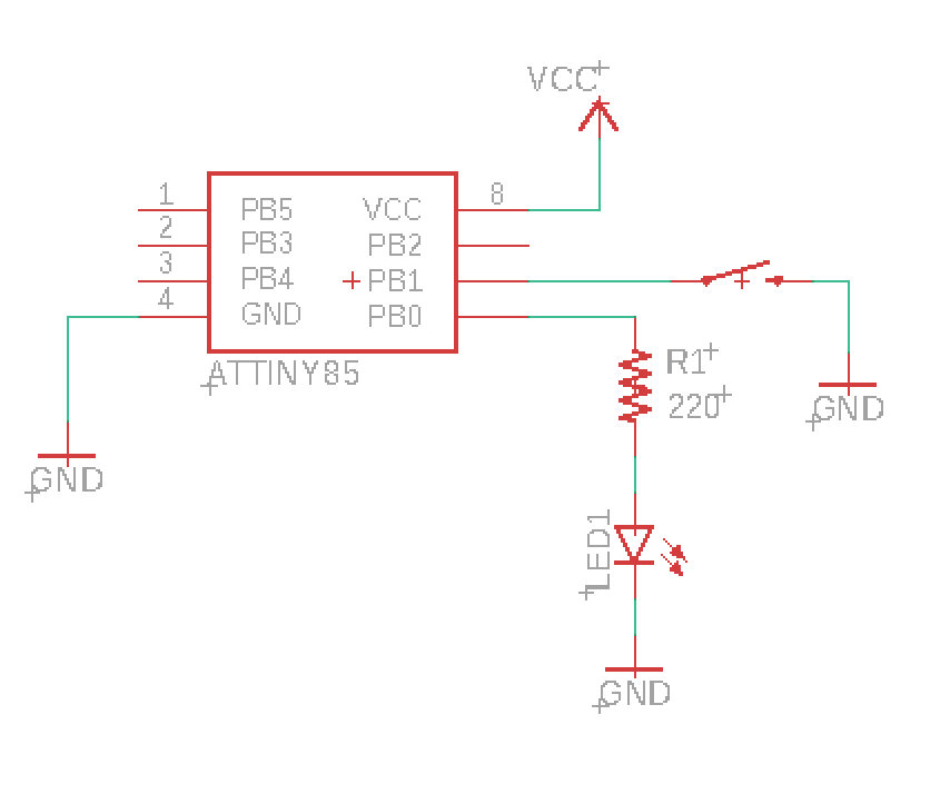 - Circuit schematic -
I used the LED as a status indicator. There is no pull-up resistor for the button as I used the microcontroller internal pull-up. An optional (recommended) component is a capacitor for debouncing the button.
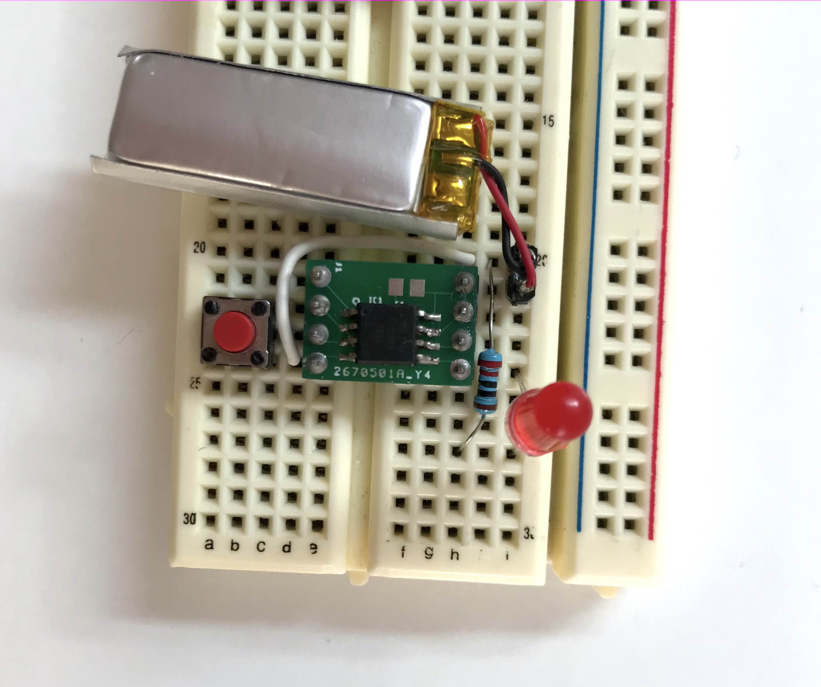 - ATtiny85 circuit on a breadboard -
Part 1 - Immediate on / off
In this scenario, when the button is pressed the micro shuts down all the peripherals and other connected hardware (lights, displays, sensors …) and then goes to sleep. When the button is pressed again, the micro is awoken. Then initializes all the relevant hardware and executes its main routine.
Program Logic
The logic here is quite simple: a variable holds the status of the device, either RUNNING or POWER_OFF. The button will trigger a pin change interrupt. When the button is pressed the ISR (Interrupt Service Routine) swaps the status. The main loop will check what is the status and either executes the main routine or puts the micro to sleep.
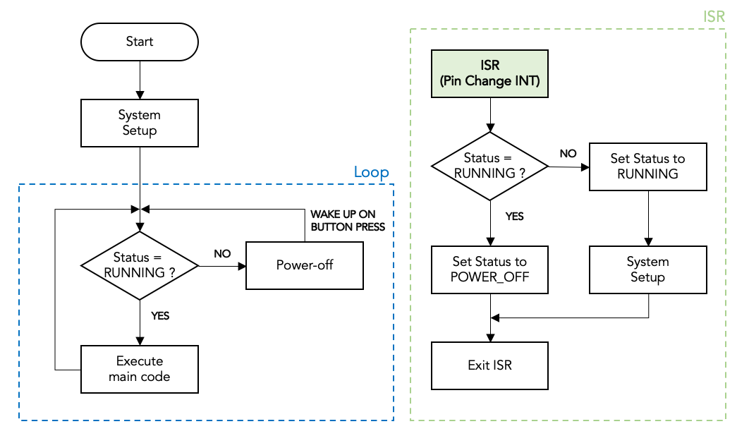 - Flowchart of the push-on / push-off code -
I report here a full working code.
#include <avr/io.h>
#include <util/delay.h>
#include <avr/interrupt.h>
#include <avr/sleep.h>
#include <avr/wdt.h>

#define BTN 1
#define BTN_STATUS !((PINB >> BTN) & 0x01)

enum Status
{
    RUNNING,
    POWER_OFF,
};

void power_off()
{
    cli();                               // Disable Interrupts before next commands
    wdt_disable();                       // Disable watch dog timer to save power
    set_sleep_mode(SLEEP_MODE_PWR_DOWN); // Set sleep mode power down
    sleep_enable();
    sleep_bod_disable(); // Disable Brown out detector
    sei();               // Enable interrupts
    sleep_cpu();
    sleep_disable();
}

Status status;  // Device status

int main()
{
    PORTB |= (1 << BTN);  // Enable PULL_UP resistor
    GIMSK |= (1 << PCIE); // Enable Pin Change Interrupts
    PCMSK |= (1 << BTN);  // Use PCINTn as interrupt pin
    sei();                // Enable interrupts

    status = RUNNING; // Start ON/OFF when power is connected

    DDRB |= (1 << DDB0); //Set pin 0 to output for the LED

    for (;;)
    {
        if (status == RUNNING)
        {
            /* main code here */

            PORTB |= (1 << PB0); // LED Pin 0 ON

            /* -------------- */
        }
        else
        {
            PORTB &= ~(1 << PB0); // LED Pin 0 OFF

            power_off();
        }
    }
}

ISR(PCINT0_vect)
{
    if (BTN_STATUS) //If button is down change status
    {
        if (status == RUNNING)
            status = POWER_OFF;
        else
        {
            status = RUNNING;
            /* initialize the device here (timers etc..)*/
        }
    }
}
Part 2 - Push-and-hold
For my project, I wanted to hold the button down for two seconds before it would turn on or off the microcontroller. This is to avoid unintentional switching. So the code above needs few adjustments.
Timer
First of all, needs a timer to record how long the button has been pressed for. The timer is set to generate an interrupt approximately every millisecond:
TIMSK |= (1 << OCIE0A); // Enable the Timer/Counter0 Compare Match A interrupt
TCCR0B |= (1 << CS01);    // Set prescaler to 8
OCR0A = 125;            // Set the output compare register so tops at 1 ms
And this is the interrupt service routine that increase the timer counter:
ISR(TIM0_COMPA_vect)
{
    timer++;
}
The timer stars every time the microcontroller is button is pressed.
Button Status
Differently from the earlier example, here I need to know what is the button status:
enum Btn_Status
{
    BTN_UP,
    BTN_DOWN,
    BTN_IGNORE
};
This status is updated every time button is pressed or released.
The BTN_IGNORE status is used to deactivate the button to avoid the device status is continuously toggled4. In fact, when the time condition is satisfied the program keeps on looping ending up in a random device status when the button is released.
if (btn_status == BTN_DOWN)
{
    if (timer > BTN_HOLD_MS)
    {
        if (status==RUNNING) status = POWER_OFF;
        else{
            status = RUNNING;
            // setup of the device here if needed;
        }
        btn_status = BTN_IGNORE; //
    }
}
Program Flow chart
This is the complete schematic for the program logic:
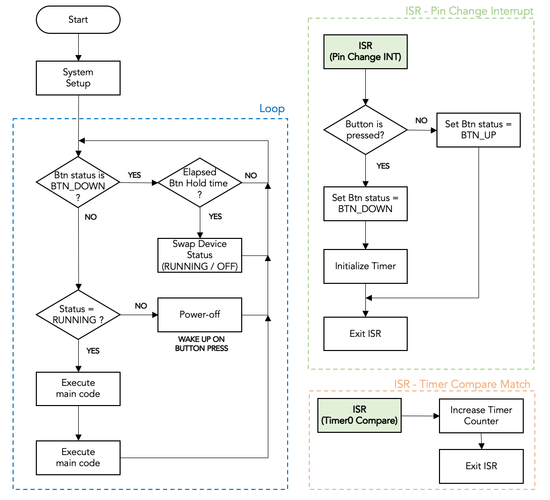 - Flowchart of the push-and-hold code -
And the entire example code:
#include <avr/io.h>
#include <util/delay.h>
#include <avr/interrupt.h>
#include <avr/sleep.h>
#include <avr/wdt.h>

#define BTN 3
#define timer_init() (TIMSK |= (1 << OCIE0A))
#define BTN_HOLD_MS 1000    // Press button for 1 second

enum Device_Status
{
    POWER_OFF,
    RUNNING
};
enum Btn_Status
{
    BTN_UP,
    BTN_DOWN,
    BTN_IGNORE
};

void setup()
{
    sei();                  // Enable interrupts
    PORTB |= (1 << BTN);    // Enable PULL_UP resistor
    GIMSK |= (1 << PCIE);   // Enable Pin Change Interrupts
    PCMSK |= (1 << BTN);    // Use PCINTn as interrupt pin (Button I/O pin)
    TCCR0A |= (1 << WGM01); // Set CTC mode on Timer 1
    TIMSK |= (1 << OCIE0A); // Enable the Timer/Counter0 Compare Match A interrupt
    TCCR0B |= (1 << CS01);  // Set prescaler to 8
    OCR0A = 125;            // Set the output compare reg so tops at 1 ms
}

void power_off()
{
    cli();                               // Disable interrupts before next commands
    wdt_disable();                       // Disable watch dog timer to save power
    set_sleep_mode(SLEEP_MODE_PWR_DOWN); // Set sleep mode power down
    sleep_enable();
    sleep_bod_disable(); // Disable brown-out detector
    sei();               // Enable interrupts
    sleep_cpu();
    sleep_disable();
}

volatile unsigned int timer;  // milliseconds counter
Btn_Status btn_status;        // Status of the button

int main()
{
    setup();
    Device_Status status = RUNNING; // Set start ON or OFF when power is connected
    btn_status = BTN_UP;
    DDRB |= (1 << DDB0); // Set pin 0 as output

    for (;;)
    {

        if (btn_status == BTN_DOWN)
        {
            if (timer > BTN_HOLD_MS) // Check if button has been pressed enough
            {
                if (status == RUNNING)
                    status = POWER_OFF;
                else
                {
                    status = RUNNING;
                    // setup of the device here if needed;
                }
                btn_status = BTN_IGNORE; // If status already changed don't swap it again
            }
        }
        else
        {
            if (status) // Is status RUNNING?
            {
                /* main code here */

                PORTB |= (1 << PB0); // Pin 0 ON

                /* -------------- */
            }
            else
            {
                PORTB &= ~(1 << PB0); // Pin 0 OFF
                power_off();
            }
        }
    }
}

ISR(PCINT0_vect)
{
    if (!((PINB >> BTN) & 0x01)) // Check if button is down
    {
        btn_status = BTN_DOWN;
        timer_init();
        timer = 0;
    }
    else
        btn_status = BTN_UP;
}

ISR(TIM0_COMPA_vect)
{
    timer++;
}
Conclusion
The code above is just an example pattern to implement a basic software power switching. Several variations are possible to accommodate different project requirements. For example:
- Push the button to turn ON and automatically turn OFF when the task is complete;
- Use sensors instead of buttons to wake up;
- Give sound feedback when turning ON or OFF;
Whatever is the use case this is an important design pattern to be aware of. If you use microcontrollers there will be a point when you need to power on and of a battery-powered project. In that case, I hope this post helped a little and you can let me know what you think in the comments.
Other posts you may be interested in
- OLED Display driven by ATtiny10
- ATtiny10 Programming with Platformio and Terminal
- Bit Bang I2C protocol
Notes
-
The ATtiny85 consumption on power-down mode with WDT and BOD disabled is just 2uA. Have a look at the ATtiny85 datasheet, Chapter 7 ↩
-
The consumption is comparable to the self-discharge of a CR2032 battery I used on the mentioned project. ↩
-
Here I make the assumption that the pin used for the button cannot differentiate between a rising or falling edge (like the Pin 5 of the ATtiny85). This is not always available and I’m describing a more general and complex case. ↩
-
An alternative is to hold the program in a loop until the button is not released. However, stopping the execution is not suitable for every situation. ↩