RunTinyRun: the smallest solar-powered game console
A solar-powered videogame console with the size of a keychain running the smallest videogame.
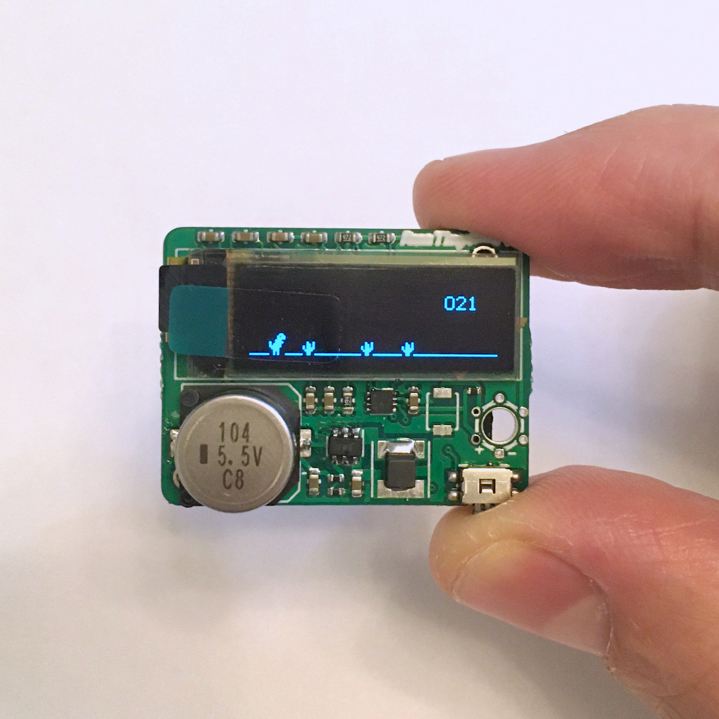
Some time ago, I wrote a videogame for the ATtiny10 that is just 780 bytes big and uses a 128x32 OLED display and one button.
I thought it deserved to leave the breadboard and get a new life on a proper PCB. I imagined it could be a good fit for an unusual keychain, but I had to solve the power issue: nobody wants to charge a keychain. Therefore I started looking at the possibility of powering it through a small solar panel.
The small solar cell I intend to use can’t generate enough power for the MCU and the display directly. The solution found is to increase the solar panel voltage by using a boost converter (MCP1640) and a supercapacitor of 0.1F acts as an energy buffer (I wrote more about it here)
When charged, the supercapacitor alone can power the device for about 30 seconds, but if it gets direct sunlight you can play for an indefinite time.
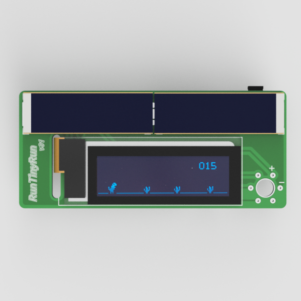
The functioning of the game is very simple: the user uses the button to jump over the obstacles that move across the screen. When he hits an obstacle the game ends.
At this point, the device goes in sleep mode to limit the power consumption.
A new game starts by pressing the button again.
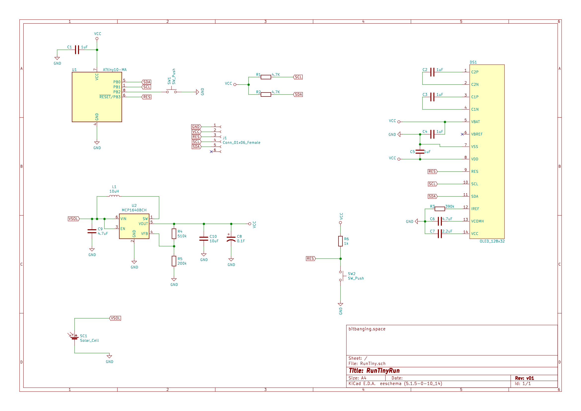
The circuit
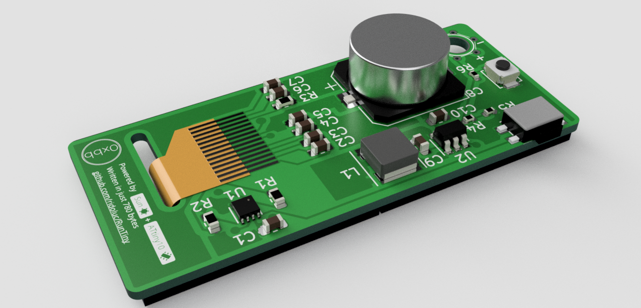
The circuit has two main blocks: the first is the game itself that comprises the ATtiny10, OLED display and a pushbutton, the second is the alimentation that includes solar panels, the boost converter and the supercapacitor.
The boost converter chosen is an MCP1640 because of its low start-up and operating voltages of 0.7V and 0.4V. A better choice (more expensive too) would be to use an energy harvesting specific chip. Maybe for the next version. The boost converter output is regulated to 3.3V and directly connected to the supercapacitor and MCU power line. I also included a small reset button in case things go wrong.
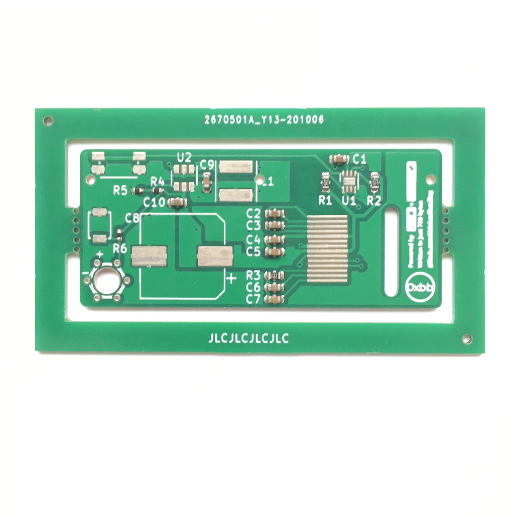
PCB Layout
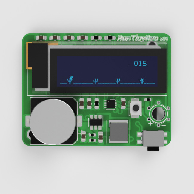
The PCB layout went through various iterations to find the most compact design. I ended up having two designs using different solar panels.
One design uses a cheap small solar panel with a size of 25x35mm. with an open-circuit voltage of 1V and a short circuit current of 80mA.
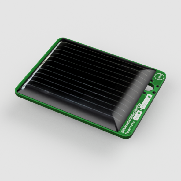
This version has all components on the front side and the panel on the back.
The second version uses two IXOLAR KXOB25-04X3F cells in parallel on the front side together with the display. All other components are on the back.
Other design considerations
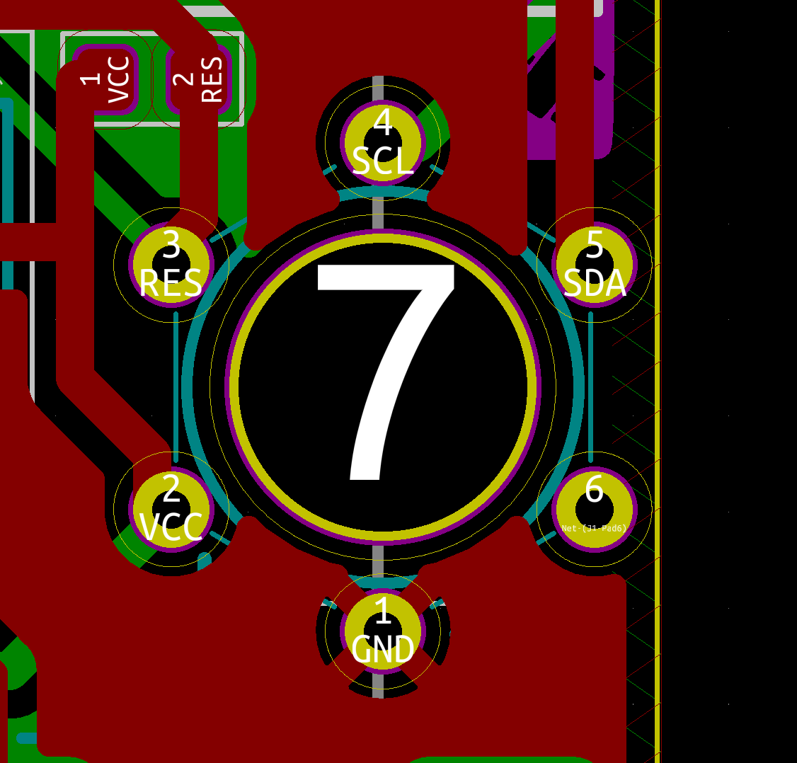
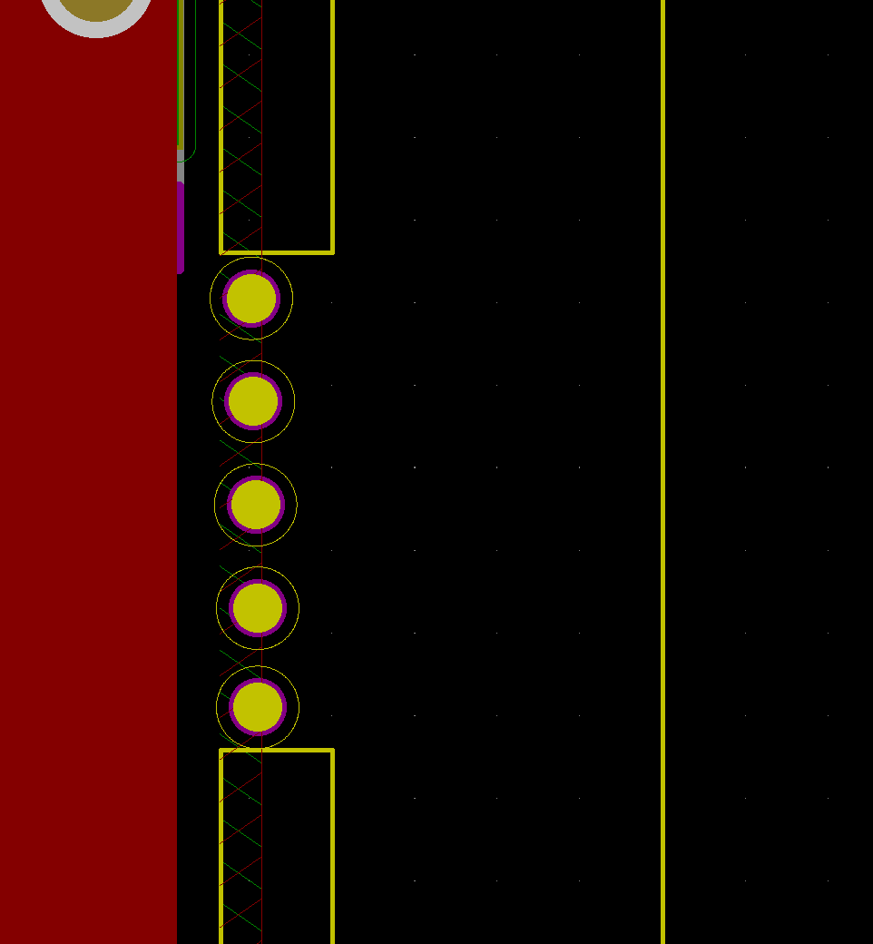
TPI Connector
I designed a circular TPI connector for programming the ATtiny10. This has six small plated through-holes placed at the vertices of a hexagon. The distance between these holes is 2.54mm so that I can build a connector with pogo-pins.
Since the board should be a keychain, a string can be attached using the large hole in the middle.
Manufacturing frame
The manufacturer is going to place two or three tooling holes on the PCB for the assembly process. There is no space on the board for these holes, so I created a frame around the PCB and connected this with two mousebites.
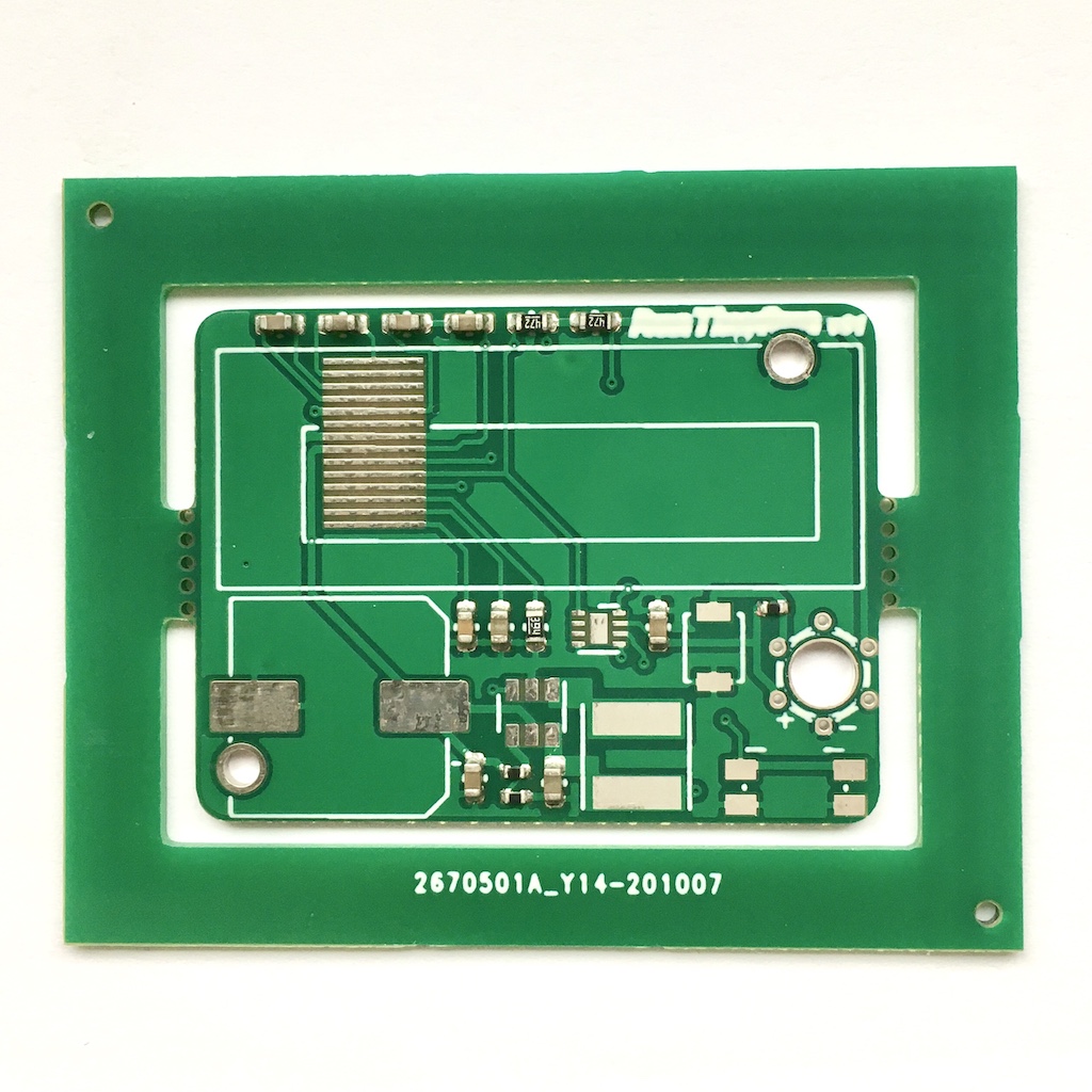
This is very simple to do in KiCad: draw two rectangles around the board on the “Edge.Cut” layer. Then connect the frame to the board with two more lines. To remove the outline on the mousebites right click on the Edge layer and select create corner. Finally add some non-plated holes.
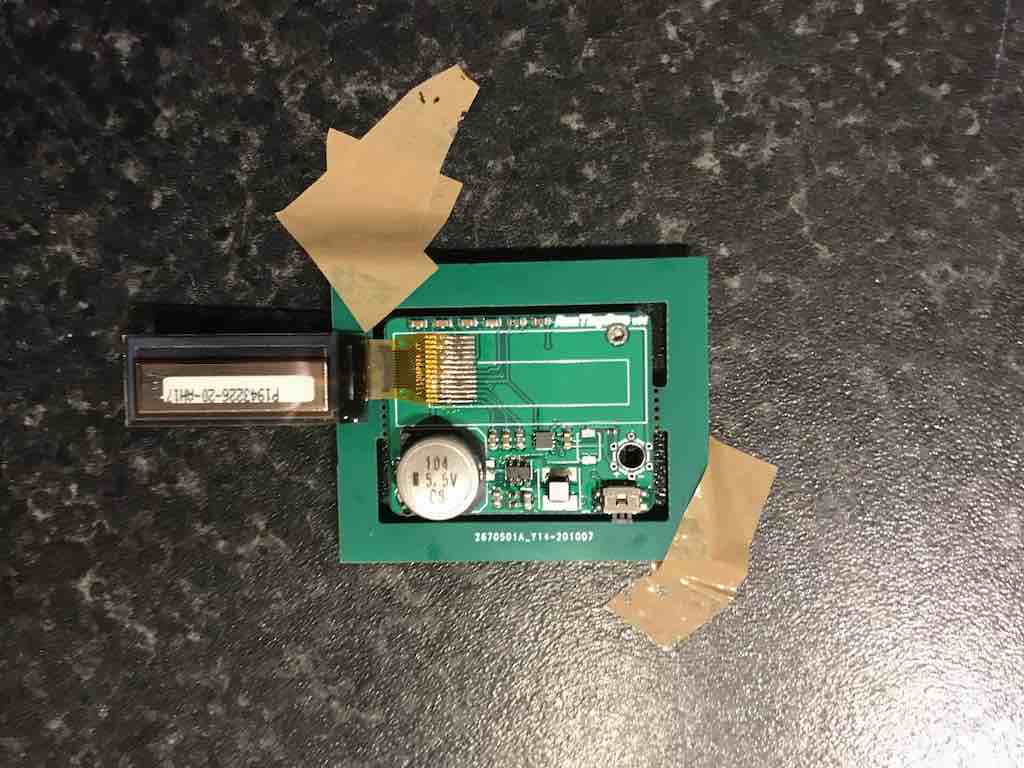
Soldering
The passive components used are mainly in a 0603 package apart from three resistors that are in 0402. I can’t bother soldering these components. I will get these assembled by the manufacturer and I will only solder the ICs, solar cells and the display.
I soldered the ATtiny10, the boost converter and the inductor using solder paste and a hot surface. I uploaded the code just after the ATtiny was soldered to make sure everything had gone right.
Soldering the 14 pin display seemed daunting at first by revealed to be simpler than I expected: use a little solder and as always a generous amount of flux helps.
Conclusions
Building this game, both software and hardware, from scratch has not been straightforward and made me learn one or two things along the way.
The result is quite neat even though some improvements are possible.
In future, I’m going to replace the MCP1640 with a solar energy harvesting specific IC to improve the charging efficiency with low light.
Another improvement will be replacing the pushbutton with a capacitive pad so that the board can be easily covered in clear epoxy.
However, for now it’s done. If you have any advice let me know in the comments.